Rice robotics club: Jumping Leg
Jumping Cat Leg Summary:
For this project I was the chief engineer, which meant I managed all of the leads and engineers on the project. I was also a technical contributor in a few mechanical areas. I guided our team through each step of the development process, suggested ideas, and provided feedback to team members.
Project inspiration:
I got the inspiration for this project when I was researching quadruped robots and noticed that none were optimized for maximum jumping height. I wanted to see what our team could do to help quadruped robots jump higher to enable them to jump over obstacles.
Initial research:
Our team started by conducting research into different types of quadruped robot mechanisms, gear reduction mechanisms, energy storage methods, and motors. From this initial research, we brainstormed solutions for components as well as the overall system. I led our effort to compare solutions and evaluate tradeoffs between different designs. This included decisions to use torsion springs for energy storage and worm gears for gear reduction. I also compiled all of the ideas we had together into one larger design, from which we could start doing CAD.
Initial prototyping:
Our next step was to create CAD models for each part and begin prototyping using 3D prints. Early on, we ran into challenges with 3D printing tolerances and timing belt slippage. Many of our components required press-fit bearings, but variations in print settings or part orientation caused slight differences in feature sizes. To address this, I developed a set of standardized printer settings and designed tolerance tester parts, allowing us to consistently print components with accurate press fits. Each part also had a defined printing orientation for reliable results.
We initially used timing belts to transfer power from the hip motor to the knee joint, aiming to reduce the leg’s moment of inertia. However, the belts often slipped under high loads, and assembling the leg with belts was cumbersome. I proposed switching to a power-transmitting shaft instead of a belt, which led us to design a second version (V2) of the leg around this idea.
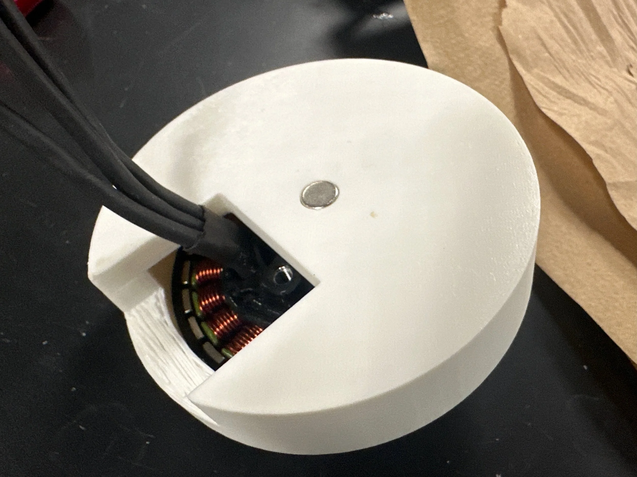
Another major challenge involved the motor encoders and controllers. The motors exhibited strange behavior, such as excessive vibration, low torque, and limited speed, which puzzled us. We discovered that a bearing, intended to align the magnet, was interfering with the magnetic field. Removing the bearing resolved the issue, but aligning the encoder magnet with the PCB became difficult without it. To solve this, I designed a jig that allowed us to precisely epoxy the magnets onto the back of the motors, ensuring accurate alignment.

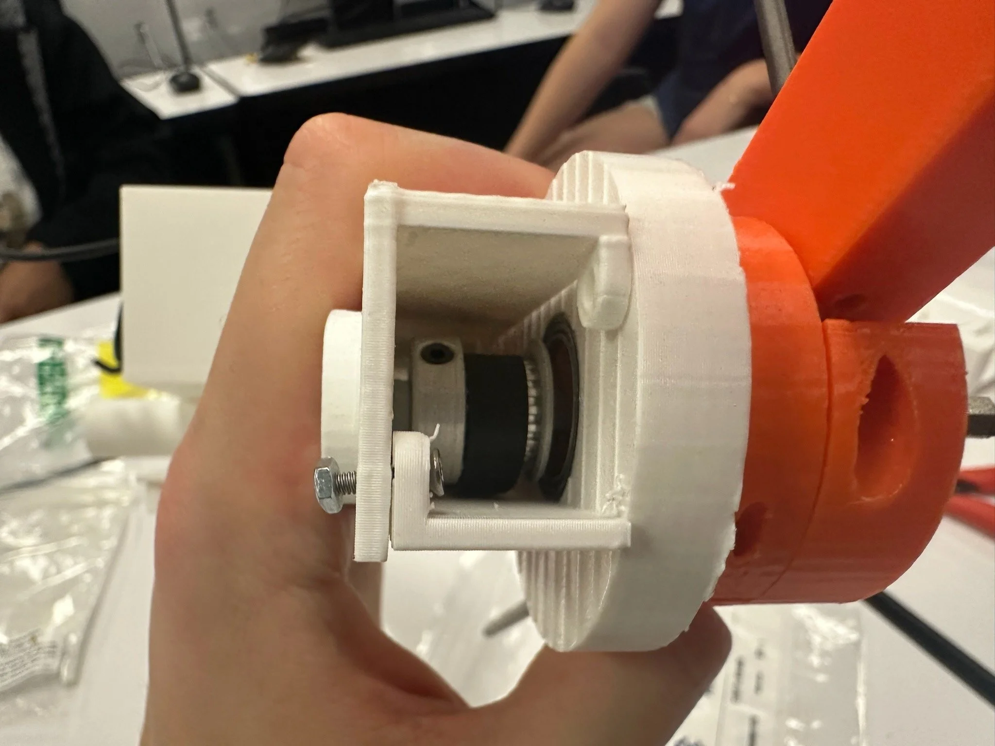
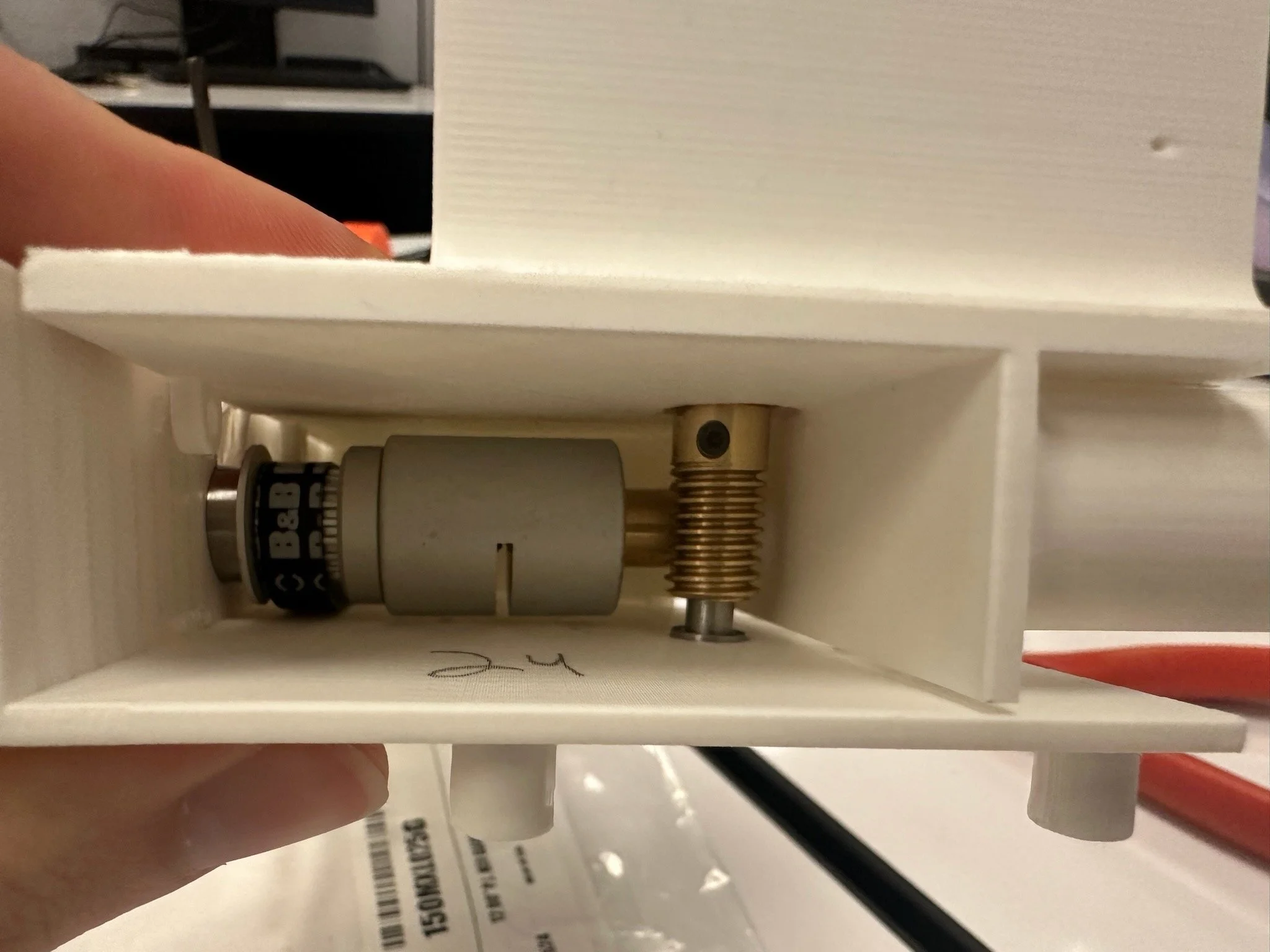
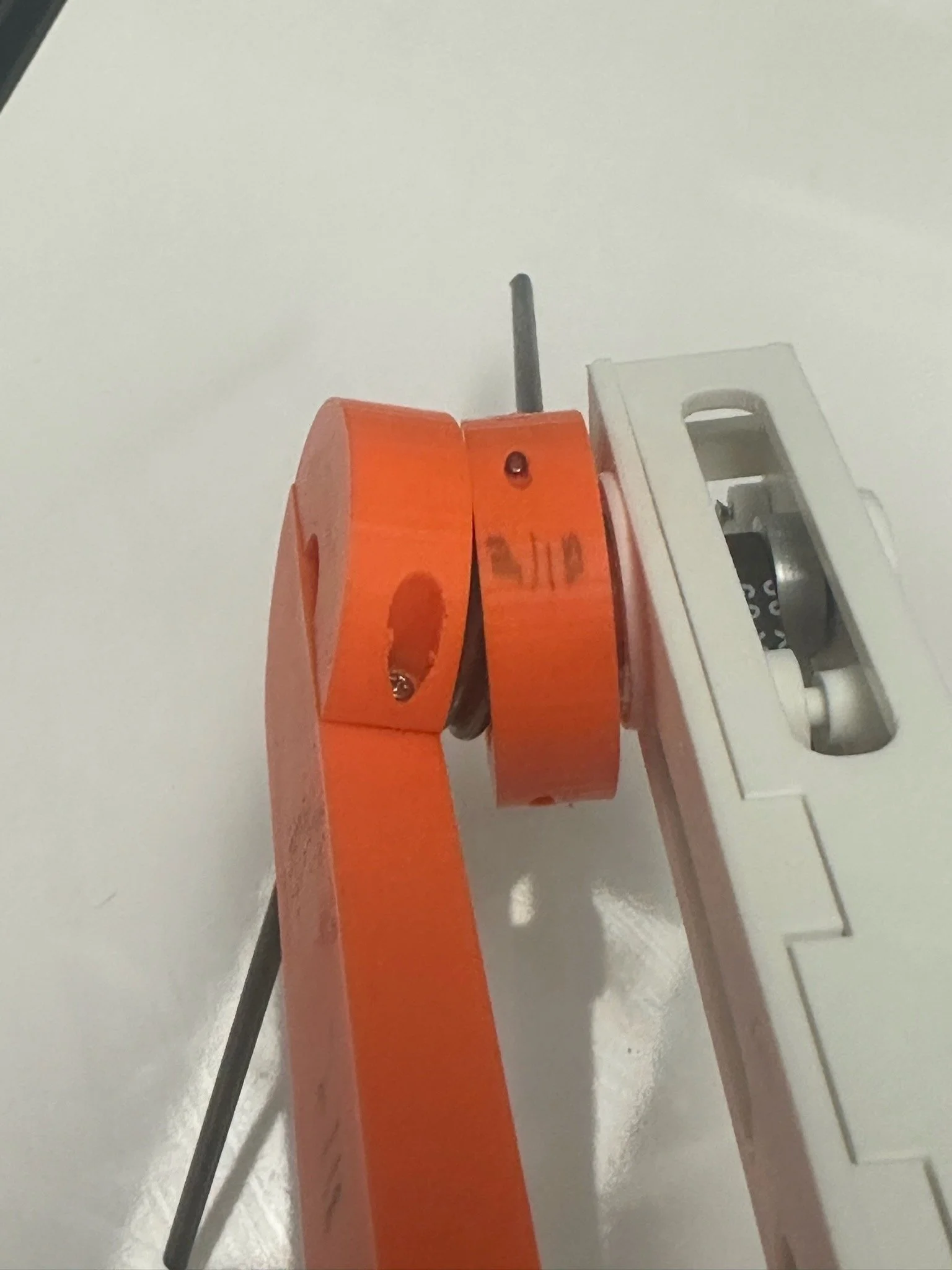
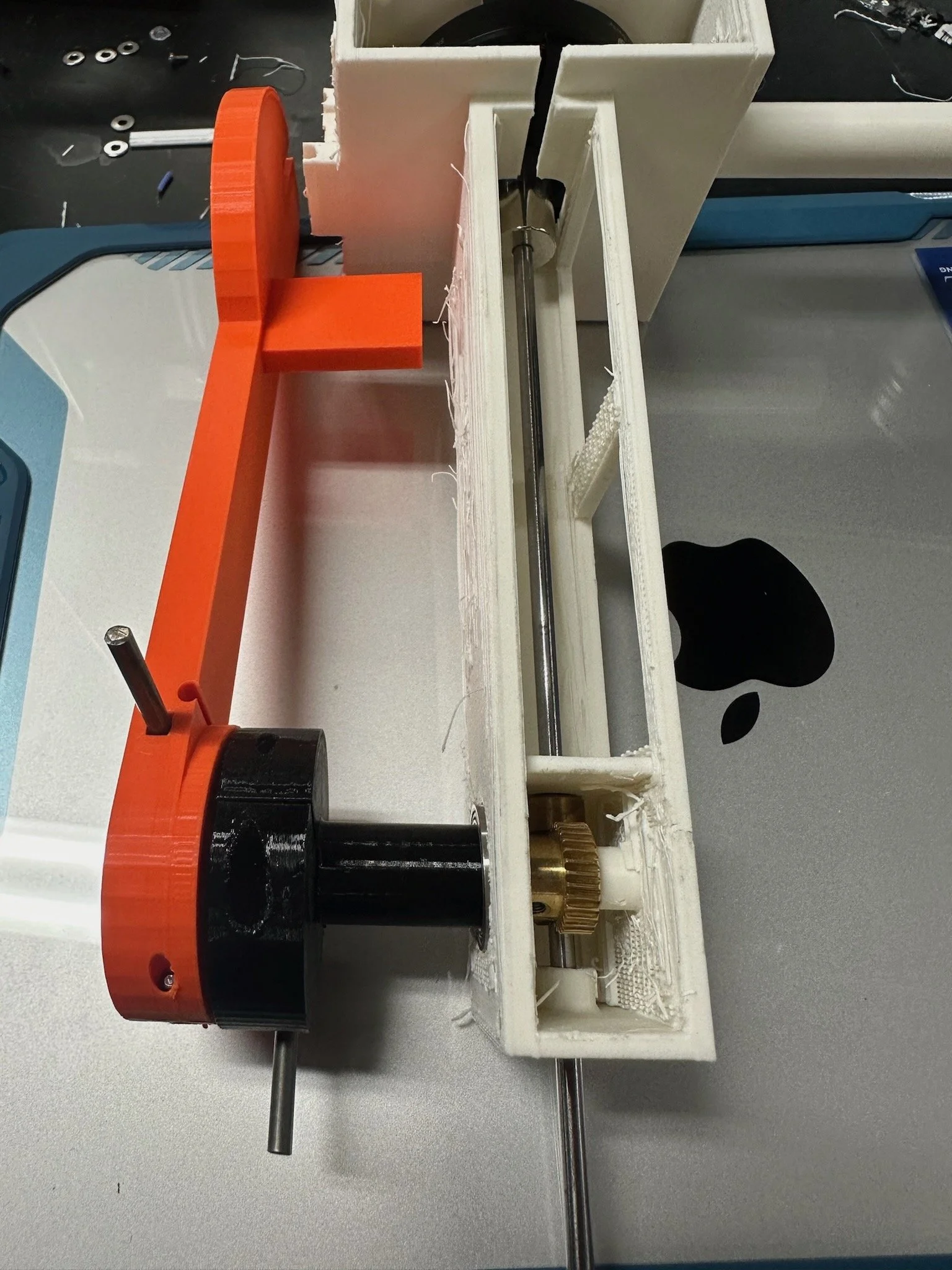
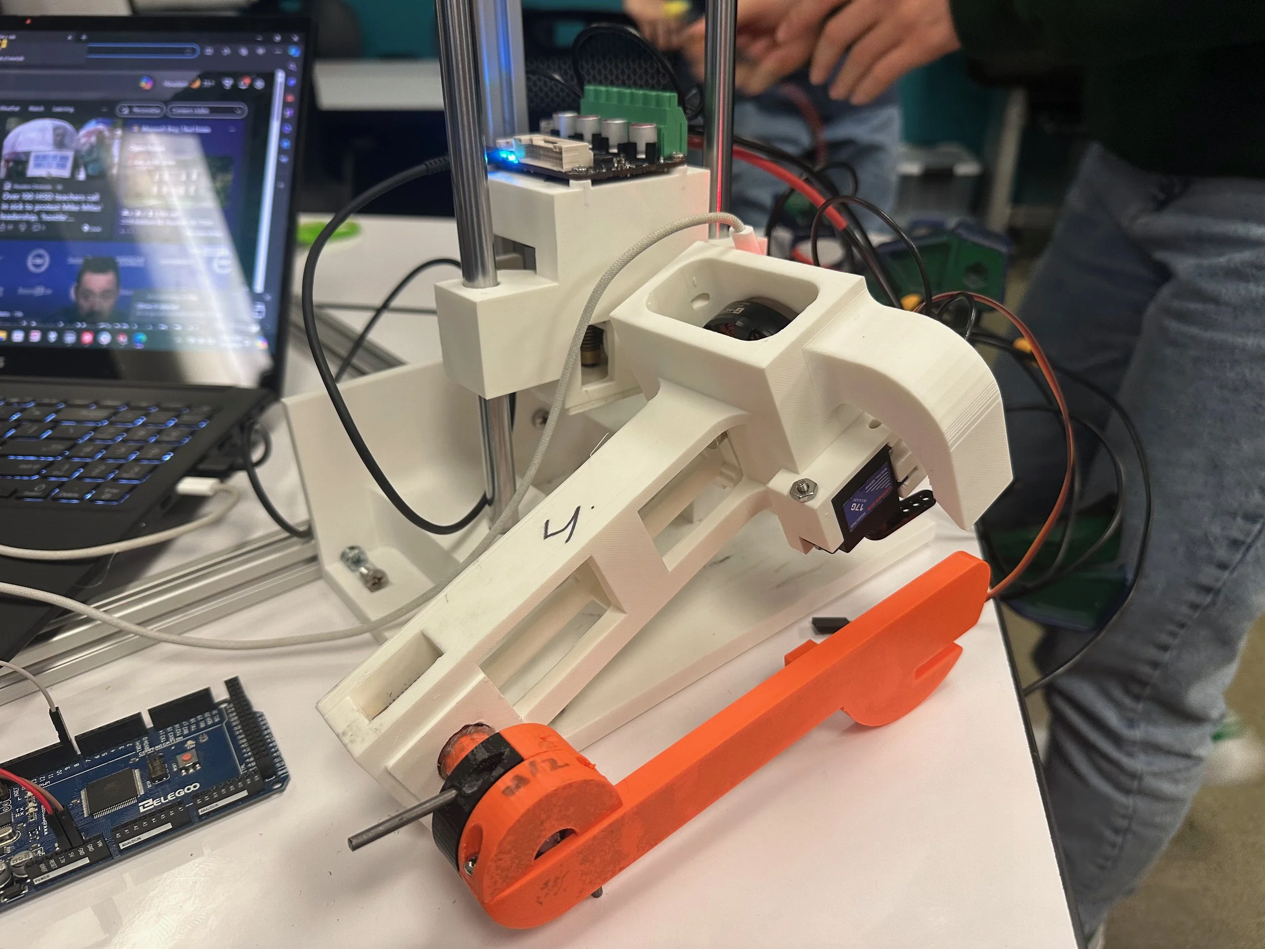
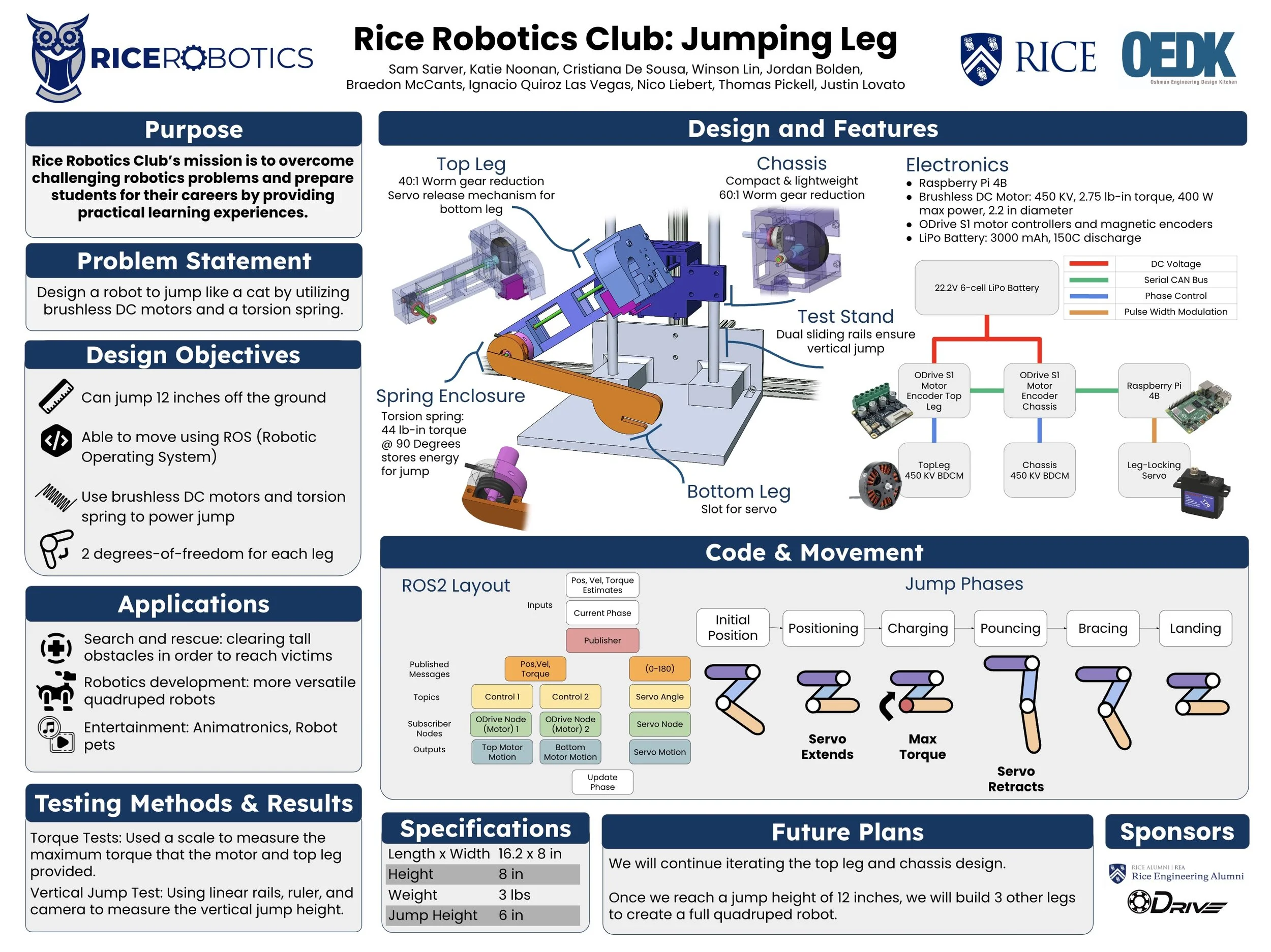
Version 2 Prototyping:
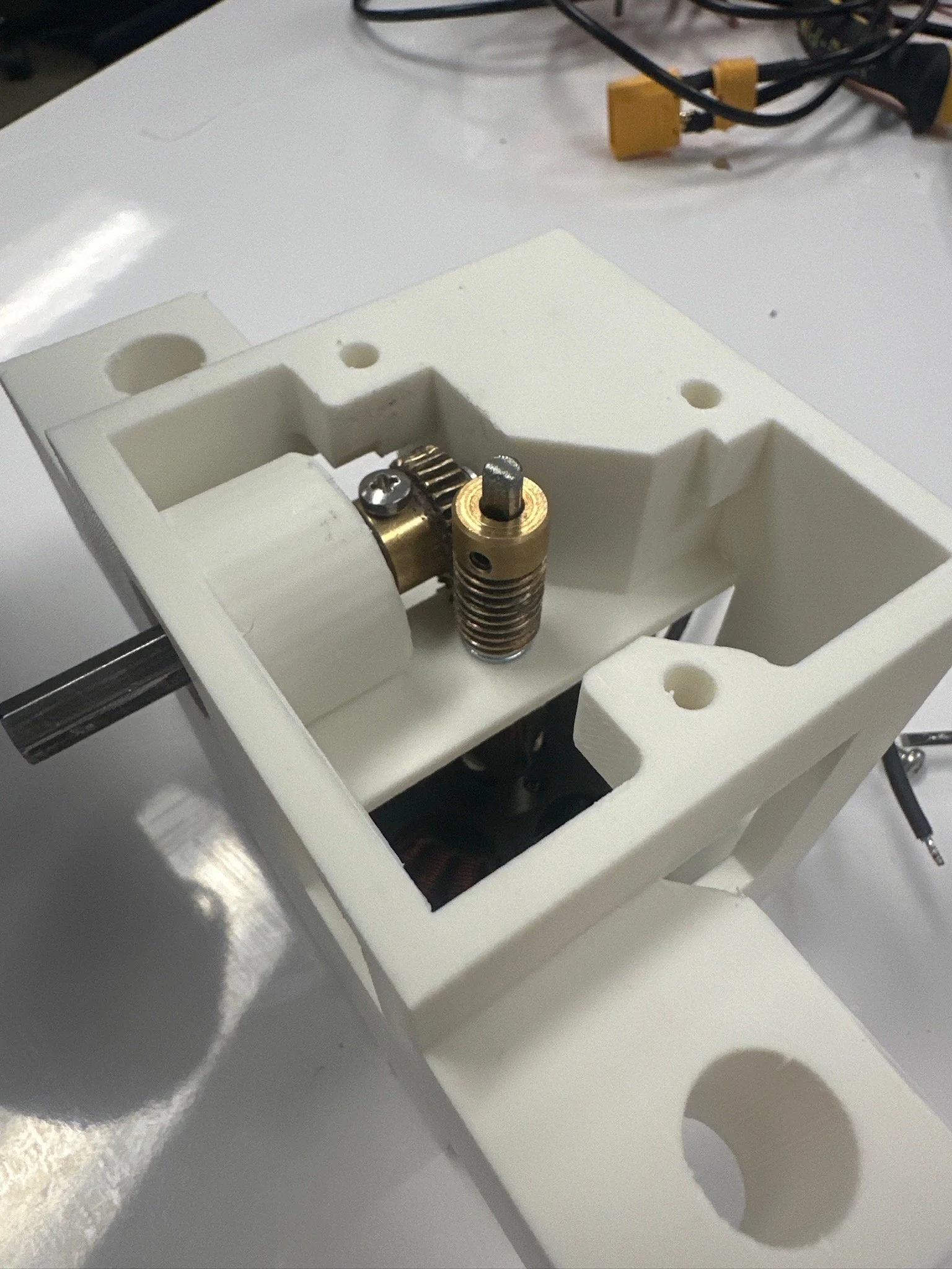
The V2 design, shown in the images to the right, introduced new challenges with worm gear alignment and skipping. The motor connected to the worm gear via a shaft, but the shaft was only supported at its two ends. As a result, the high radial loads from the worm gears caused the shaft to bend, leading to gear slippage. I addressed this issue by adding an additional bearing along the shaft to reduce deflection.
I also underestimated the axial loads generated by the worm gear, which caused components to shift out of place, leading to the leg falling apart after a few tests. Additionally, we encountered efficiency issues with the worm gears—they were far less efficient than expected. To compensate, we had to use a much higher gear reduction than originally planned.
End results and next steps:
At the end of last semester, we successfully tested the spring charging and release mechanism, achieving a jump height of 6 inches powered solely by the energy stored in the torsion spring. This jump height corresponds to an energy efficiency of 13%, based on the energy used to charge the spring versus the resulting jump height.
The project is continuing this semester, with a focus on exploring leg designs that incorporate linkages to keep both motors inside the chassis. We are also investigating more efficient gear reductions, such as cycloidal drives.